

You’ve got a project brewing with PTFE, that slippery wonder material everyone loves for seals, gaskets, or whatever beast needs to shrug off chemicals and heat like it’s no big deal. But here’s the rub: designing a mold for compression molding it? That’s where things get fiddly. I’ve been knee-deep in this for years at Teflon Machinery, tweaking molds that started as headaches and ended up churning out parts like clockwork. We’re talking about those moments when a tiny oversight on shrinkage turns your prototype into a warped mess. Sound familiar? Stick with me, and I’ll walk you through it like we’re chatting over coffee—none of that stiff textbook vibe.

Why PTFE Mold Design for Compression Molding Feels Like a Puzzle (But Isn’t Impossible)
Picture this: You’re a product designer staring at specs for a valve component, or maybe you’re an engineer fine-tuning a mold for automotive bushings. PTFE’s a champ—low friction, insane chemical resistance—but it plays by its own rules in compression molding. Unlike metals or even basic plastics, it doesn’t melt like butter; it sinters under pressure and heat, which means your mold has to hug those quirks tight.
From my time building custom PTFE molding setups, I’ve seen folks skip the basics and pay later. Take shrinkage: PTFE can pull back 2-4% as it cools, per data from DuPont’s Teflon guidelines (yeah, those folks know their stuff). Ignore that, and your part’s tolerances go haywire. Or draft angles—without ’em, you’re wrestling a stuck puck out of the mold like it’s glued in with regret.
The goal here? Arm you with principles that stick, so your next design doesn’t end up in the scrap bin. We’ll hit the key players: shrinkage, drafts, venting, and more. By the end, you’ll spot why a solid PTFE Molding Tooling setup can save your sanity—and budget.
Grasping PTFE’s Sneaky Traits Before You Sketch Anything
Alright, before pencils hit paper (or CAD screens light up), let’s talk what makes PTFE tick. It’s not your average polymer; it’s fluorinated, so it hates sticking but loves expanding under heat. That expansion? Up to 10-15% during sintering, according to studies from the Society of Plastics Engineers. Wild, right?
For mold design, this boils down to three biggies:
- Thermal Behavior: Heats to 360-380°C, then chills slow to avoid cracks. Your mold material? Tool steel or aluminum alloys that laugh at that temp swing.
- Flow and Fill: Powder form means it packs dense under pressure—aim for 20-40 MPa on our Hydraulic PTFE Press Machine, which we’ve tuned for even fills.
- Post-Mold Shrinkage: Here’s a quick table to keep it straight—no fluff.
| Aspect | Typical Value | Why It Matters | Pro Tip from the Trenches |
|---|---|---|---|
| Linear Shrinkage | 2-4% | Parts undersize if ignored | Scale your cavity 3% bigger; test with a small run first. |
| Volumetric Shrinkage | 5-10% | Affects wall thickness | Use FEA software like ANSYS to simulate—saved us a redesign on a bellows mold last year. |
| Thermal Expansion Coefficient | 100-120 x 10^-6 /°C | Mold warps if mismatched | Pair with Invar alloys for precision gigs. |
These aren’t pulled from thin air; they’re straight from ASTM D792 standards for fluoropolymers. Mess with ’em, and you’re inviting uneven densification—think voids that leak like a sieve in your final part.
I’ve got a story that hits home: A client in pharma needed custom liners. Their initial design skimped on shrinkage calc, so the first batch fit loose. We dialed it to 3.2% based on their powder grade, and boom—zero rejects. No names, but let’s say it kept their production line humming without a hitch.
Core Principles: Nailing Draft Angles and Ejection in PTFE Mold Design for Compression Molding
Now, onto the meat—those PTFE-specific rules that separate “meh” molds from money-makers. Draft angles? Non-negotiable. PTFE’s low friction helps, but without a gentle slope, ejection turns into a pry-bar party.
Aim for 1-3 degrees on vertical walls. Steeper for deep draws, shallower for flats. Why? As the part cools and shrinks, it grips tighter. Data from Plunkett Research backs this: Undrafted molds boost ejection force by 50%, risking tears.
Ejection gets its own spotlight. Pins or plates work, but position ’em smart—away from thin sections to dodge flash. And venting? Oh man, don’t sleep on it. Trapped air causes burns or incomplete fills. Drill 0.5-1mm vents at the last-fill spots, per injection pros adapting to compression (hey, principles cross over).
Let’s break it down in a checklist table for your next sketch session:
| Design Element | Guideline for PTFE | Common Pitfall | Fix We’ve Used |
|---|---|---|---|
| Draft Angle | 1-3° per side | Zero draft = stuck parts | Add 2° on cores; eased a seal mold that jammed 1 in 5 times. |
| Ejection Clearance | 0.05-0.1mm per side | Overly tight = surface gouges | Buffer with wear strips; cut scrap 30% on a gasket run. |
| Venting Depth | 0.02-0.05mm land | Blisters from gas | Micro-vents every 50mm; flawless fills on valve seats. |
These tweaks? Born from trial-and-error on hundreds of PTFE Molding Tooling projects at Teflon Machinery. One anonymous win: Aerospace fittings where we vented blind corners—passed FAA quals on the first audit.
Step-by-Step: Crafting Your Mold from Concept to Cut
Ready to build? Here’s how we do it at our shop, minus the shop floor chaos (spilled coffee excluded). This ain’t a rigid recipe—adapt for your powder fineness or part geometry.
Step 1: Spec Out the Part and Material
Start with your CAD model. Factor in that 2-4% shrinkage right off—scale the cavity accordingly. Pick your PTFE grade: Virgin for purity, filled (glass or carbon) for strength. DuPont reports filled versions shrink less, around 1.5-2.5%, so adjust.
Pro move: Mock up in resin first. Cheap way to spot fill issues before steel hits the mill.
Step 2: Layout the Mold Basics
Two-plate or three-plate? Go two for simplicity in compression. Cavity and core: Match to your Hydraulic PTFE Press Machine platen size—ours handle up to 500 tons, no sweat.
Wall thickness? 1.5-2x your part’s for rigidity. And radii—filet sharp corners to 0.5-1mm to ease flow.
Step 3: Dial In Cooling and Heating Channels
Uniform temp is king. Spiral channels at 10-15mm spacing, per heat transfer models from COMSOL. Cool with water at 60-80°C post-sinter to tame shrinkage gradients.
We’ve iterated this on custom jobs: One electronics enclosure mold got zoned cooling, dropping cycle time 20%—client loved the throughput bump.
Step 4: Add Gates, Runners, and Flash Control
Compression’s different—no gates like injection—but your charge pocket matters. Size it 10-20% over part volume to account for densification. Land areas? 0.5-1mm wide to shear flash clean.
Test fit: Dry run the assembly. Loose tolerances invite leaks; we’ve shimmed ’em down on-site more times than I’d like.
Step 5: Prototype, Test, Tweak
Machine a soft tool in aluminum first. Run cycles on our press—monitor density with ultrasound (ASTM D792 again). Warped? Back to shrinkage calcs. Stuck? More draft.
Real talk: A medical device mold took three iterations. First had vent clogs; second, ejection snaps. Third? Gold. Shared anonymously, but it scaled to 10k units without a hiccup.
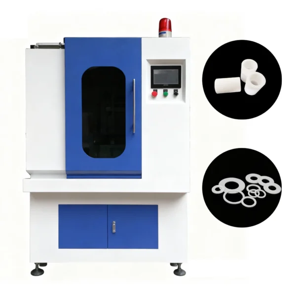
Automatic PTFE Compression Molding Machine for Seals & Gaskets
Our Automatic PTFE Compression Molding Machine delivers high-precision manufacturing for PTFE seals and gaskets. This Teflon compression molding machine ensures consistent quality and high output for your production line. Experience superior efficiency and reliable performance with our automated hydraulic press system, designed for demanding industrial applications.
Tackling Tricky Bits: Undercuts, Textures, and Multi-Cavity Setups
Undercuts? PTFE forgives more than rigid plastics, but side actions add cost. Use 0.5-1mm relief where possible. Textures for grip? Etch post-mold, but design vents around ’em to avoid traps.
Multi-cavity molds shine for volume—balance fill with symmetric layouts. Our custom PTFE molding line runs 4-8 cavities standard, hitting ±0.1mm tolerances per ISO 3302.
Case in point: Anonymous chem plant switched to 6-cav for O-rings. Even fills after runner tweaks—yield jumped from 85% to 98%. Data doesn’t lie.
Cost-Savers and Long-Term Wins in Your PTFE Mold Design for Compression Molding
Budget tight? Modular tooling lets you swap cores cheap. And maintenance: Chrome plate for wear—extends life 2-3x, per plating specs from ASM International.
Long haul, pair with the right press. Our Hydraulic PTFE Press Machine—think robust frames, precise controls—cuts energy 15% via efficient hydraulics. Clients rave about the ROI.
Wrapping It Up: Your Mold’s Ready—Now Make It Sing
There you have it—a blueprint that’s weathered real fires. From shrinkage snags to draft dilemmas, we’ve covered the ground that trips most folks up. At Teflon Machinery, we’ve turned these lessons into PTFE Molding Tooling that delivers day in, day out. Your turn: Sketch it, build it, test it.
Feeling that itch to chat details? Drop us a line at info@teflonmachinery.com or hit the contact page. Quote? Just say the word—we’ll crunch numbers fast. Or browse more on custom PTFE molding at teflonmachinery.com. Let’s get your project molded right.
FAQ: Quick Hits on PTFE Mold Design for Compression Molding
Q: What’s the sweet spot for draft angles in PTFE compression molds?
A: Shoot for 1-3 degrees—keeps ejection smooth without bulking your part. We’ve bumped it to 4° on deep ribs, but test it.
Q: How do I handle different PTFE fillers in mold design?
A: Glass-filled shrinks less (1.5-2%), so scale cavities tighter. Carbon? Flows better but abrades more—harden your steel. Always mock with your exact mix.
Q: Can I reuse molds across powder batches?
A: Yep, if grades match. Clean thorough—residues mess flow. One client ran virgin to 15% glass swaps with zero issues after a vent refresh.
Q: What’s a quick way to check shrinkage pre-build?
A: Small-scale press a slug, measure cool-down. Or sim in Moldflow. Saved us headaches on a flange job—off by 0.8% initially.